The development direction of vehicle mounted radar
In the coming years, radar technology will play a key role in the evolution of advanced driver assistance systems (ADAS). With the continuous expansion of its functions, the transmission and reception modules, signal processing mechanisms, and automatic risk avoidance capabilities of radar will gradually enable vehicle ADAS systems to possess characteristics similar to tactical systems on fighter jets, thus having a profound impact on the design of automotive systems.
Why radar?
In a recent interview, Reuter mentioned: “It is worth noting that in ADAS sensing technology, only the radar is not affected by weather conditions. Although cameras perform well in target recognition, radar is even better at detecting objects and measuring their speed Reuter explained that because of this, many early systems that focused on object detection and risk classification tended to adopt radar technology. He also mentioned, “In Europe, there is a strong demand for emergency braking systems for trucks, and these systems are based on radar
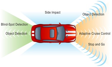
The radar system will first deploy a medium range forward-looking device to monitor the road conditions ahead. However, this system will soon evolve into a form of multi-sensor fusion, which includes not only long-range forward vision capabilities, but also short-range sensors for comprehensive hazard assessment, as shown in Figure 1.

Figure 1. The radar system is capable of conducting forward search and observing the surroundings of the vehicle.
Although optical vision systems are already quite mature, the advantages of radar systems will further enhance their performance. Reuter predicts that in the near future, multi camera systems with target recognition capabilities will be able to integrate video and radar data to construct dynamic models of the surrounding environment.
Collect signals
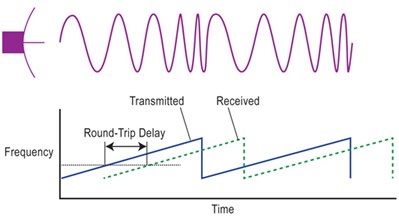
To understand the impact of radar on automotive system design, it is first necessary to understand the role of sensors. Most automotive radar systems tend to use the unlicensed frequency bands of 24 GHz or 77 GHz. The transmitter of radar usually adopts the design of frequency modulated continuous wave (FMCW), which emits a rapidly changing signal in the frequency domain, commonly known as “chirp”, as shown in Figure 2.

Figure 2. The onboard radar will use chirped FMCW.
Reuter explained, “The biggest advantage of FMCW is that it simplifies the process of interpreting reflected signals. It can directly obtain the distance information of the target from the reflected frequency and infer the velocity of the target from the Doppler shift. Compared to pulse modulation schemes, generating continuous waves (CW) is simpler, easier to understand, and ensures reliability, which is what car manufacturers are most concerned about because they believe that every euro invested in ADAS improvements is directly related to corporate profits
The design of receiving signals also requires low-cost and innovative methods. In order to collect directional information, reflected signals can be obtained through mechanical scanning antennas or phased array antennas, and are usually combined with digital beamforming algorithms. Multiple channel homodyne receivers are often equipped behind the antenna to meet the requirements of antenna design – for example, a simple rotating antenna array may contain 16 channels.
Reuter added, “The output signal of the receiver is a baseband signal in the DC to 20 MHz range.” To achieve a system design with good azimuth resolution, 8 to 16 channels may be required, and correspondingly 8 to 16 high-speed analog-to-digital converters (ADCs) are needed.
Extracting information from chirps
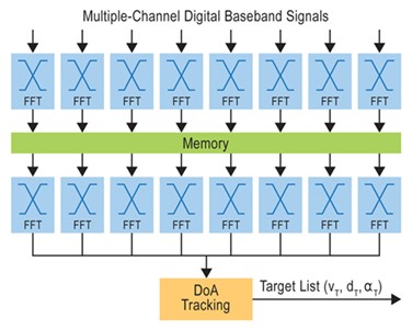
The digital baseband signal generated by each channel will be input into the Fast Fourier Transform (FFT) module for processing, with a transform length of up to 2K sample points. Reuter said, “In the past, performing FFT required a large amount of FPGA. Now, the trend is to use 32-bit microcontrollers with integrated floating-point DSP accelerators.” Through the dual FFT module, the beamforming system can extract distance and velocity data from the signal, as shown in Figure 3.

Figure 3. FFT configuration for beam focusing and range and velocity estimation.
In fact, the front-end processing unit is responsible for processing multiple input FMCW analog signal channels and converting them into a digital data stream containing azimuth, distance, and velocity information. This data stream will then be transmitted to one or more CPU cores, where software supported by a series of accelerators will analyze the data to detect objects around the vehicle, determine their location and attributes.
Reuter explained, “You need to identify these targets, distinguish them from the background noise, and then select the most critical one. As you may need to process up to 200 targets, the computational task is very heavy, especially when extracting angle information
The physical layout of the system is also becoming increasingly complex. According to Reuter, current sensors themselves do not undertake too many processing tasks. On the contrary, ADCs are equipped with dedicated analog interfaces, while dedicated digital interfaces are used for signal processing hardware such as FFT processing. In addition, the microcontroller is also connected to other interfaces for extracting and classifying targets. These target information will ultimately be transmitted to the vehicle’s CAN or FlexRay bus for the central CPU cluster to parse and analyze.
The entire processing flow imposes strict requirements on bandwidth and latency. Reuter pointed out that the CPU’s analysis of data is usually presented to the driver in graphical form, that is, through a multifunctional display integrated with the windshield. This mixed display method requires that the update interval should not exceed 50 milliseconds, and the maximum delay should also be controlled within 50 milliseconds, otherwise the image will become unstable, resulting in screen delay and possible driver misjudgment.
As the system evolves from a single sensor to a multi-sensor that supports beamforming and achieves fusion with camera data, the interconnection architecture also changes accordingly. Reuter stated, “There is a need to use Ethernet to reduce connection costs.” However, as the system still needs to run in real-time, this raises new questions about how to ensure Ethernet real-time performance.
A future full of distractions everywhere
When there are no other vehicles using the radar around, the onboard radar system is usually reliable. However, as more and more vehicles are equipped with radar systems, mutual interference between devices becomes difficult to avoid. Reuter pointed out that interference can be reduced by changing the modulation rate, ultimately leading to the use of coded frequency hopping patterns instead of simple frequency changes, so that each vehicle can recognize the “chirp” signals it emits. This method can achieve complex extraction and analysis of reflected signals while maintaining the original system architecture and most of the hardware unchanged.
Additionally, there is a tricky issue arising from the interference caused by fixed facilities. Reuter reminds that some tunnels in Europe use high-power radar to detect vehicles, which can cause a problem as their transmitters can affect the normal operation of onboard radar
Another more subtle issue involves astronomical observations. The 77GHz frequency band contains the critical spectrum required for astronomical observations, and in densely populated areas, the increasing number of onboard radars can cause serious interference to astronomical radio signals.
Reuter also mentioned, “In Japan, there are regulations requiring the shutdown of transmitters within a 1000 kilometer radius of radio telescopes, which almost covers the entire country
Whether it’s chirp modulators, digital beamforming, target recognition, risk assessment, frequency hopping protection, or interference management – these sound more like technical features of modern fighter jets than the functions of ordinary trucks and cars. In fact, ADAS has indeed borrowed many technologies from military systems. Considering the increasingly harsh weather conditions and severe traffic congestion, this metaphor is not unreasonable.
