Basic principles of ranging and speed measurement for FMCW radar
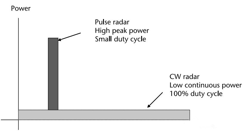
Radar can be classified into pulse radar and continuous – wave radar according to the type of transmitted signals. Conventional pulse radar transmits periodic modulated pulse signals, while continuous – wave radar transmits continuous – wave signals. Generally, pulse radar has a high peak power and a small duty cycle, while continuous – wave radar has a 100% duty cycle and a lower power.

FMCW radar is very useful in scenarios where high – resolution is required under low – transmission – power conditions. It is applied in automotive radar, short – range imaging, and many other application scenarios.
FMCW Radar Basics
The transmitted signal of continuous – wave radar can be either single – frequency continuous – wave (CW) or frequency – modulated continuous – wave (FMCW). There are various frequency – modulation methods, such as triangular – wave modulation, saw – tooth – wave modulation, code modulation, or noise frequency – modulation. Single – frequency continuous – wave radar can only be used for velocity measurement and cannot measure distance, while FMCW radar can measure both distance and velocity, and its advantages in short – range measurement are becoming more and more obvious.
FMCW radar transmits a continuous – wave with a changing frequency during the frequency – sweep period. The echo signal reflected by an object has a certain frequency difference from the transmitted signal. By measuring this frequency difference, the distance information between the target and the radar can be obtained. The frequency of this beat – frequency signal is relatively low, generally in the range of KHz. Therefore, the hardware processing is relatively simple, which is suitable for data acquisition and digital signal processing. The simple block diagram is as follows:

The high – frequency signal is generated by a voltage – controlled oscillator. Part of the signal is fed to the transmitting antenna after additional amplification through a power splitter, and the other part is coupled to the mixer. It is mixed with the received echo signal, and then low – pass filtered to obtain the base – band beat – frequency signal. After analog – to – digital conversion, the signal is sent to the signal processor for processing.
Ranging/Velocity – Measurement Principles
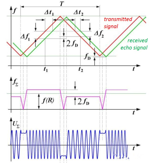
The following takes the triangular – wave frequency – modulated continuous – wave as an example to briefly introduce the ranging and velocity – measurement principles of the radar. In the figure below, the red line represents the frequency of the transmitted signal, and the green line represents the frequency of the received signal. The frequency – sweep period is T, the frequency – sweep bandwidth is B. After the transmitted signal is reflected by the target, the echo signal will have a time delay. In the triangular – wave frequency change, distance measurement can be carried out on both the rising edge and the falling edge.

If there is no Doppler frequency, the frequency difference during the rising edge is equal to the measurement value during the falling edge. For a moving target, the frequency differences during the rising/falling edges are different. We can calculate the distance and velocity through these two frequency differences.
The beat – frequency signal is low – pass filtered and amplified, and then sent to the digital signal processor. The FFT and detection of the beat – frequency signal are completed, and the target data is processed and then sent to the display and control terminal for display. The triangular – wave frequency – modulated continuous – wave radar eliminates the coupling between distance and velocity by using positive and negative frequency – modulation slopes, and then estimates the target velocity.
However, in order to obtain the velocity information of the target, the radar usually sends out a series of chirp signals at uniform equal – time intervals in units of frames. Then, the velocity of the target in the target field is measured by using the signal phase difference. A distance FFT is performed on the digitized sampling points corresponding to each chirp, and the output results are stored in a matrix in the form of continuous rows. After the processor receives and processes all the single chirps in a frame, it starts to perform an FFT (Doppler FFT) on the chirp sequence.
The combined operation of the distance FFT (row – by – row) and the Doppler FFT (column – by – column) can be regarded as a two – dimensional FFT of the digitized sampling points corresponding to each frame. The two – dimensional FFT can simultaneously distinguish the distance and velocity of the target. That is, the peak position of the two – dimensional FFT corresponds to the distance and velocity of the target in front of the radar.
The analysis of the target angle information requires multiple RX antennas. Therefore, the processor first processes the signals received by each antenna with a two – dimensional FFT. Subsequently, the two – dimensional FFT matrices obtained from multiple antennas are jointly processed, and finally the angle of arrival of the target is obtained.
Through the above processing, the radar can analyze multi – dimensional information such as the distance, velocity, and angle of the target. The performance indicators of the radar depend on the choice of the transmitted signal. For example, as the bandwidth of the chirp signal increases, the range resolution increases; the velocity resolution increases as the frame duration increases.
Similarly, the maximum measurable velocity is inversely proportional to the spatial interval between adjacent chirp signals; the number of TX/RX antennas plays a decisive role in the angular resolution. The effective noise bandwidth of the FMCW radar is inversely proportional to its frequency – modulation time. The longer the frequency – modulation time, the lower the effective noise bandwidth and the higher the resolution.
Continuous – wave frequency – modulated (FMCW) radar has been widely used in the automotive field, covering various aspects from safety to comfort performance, such as blind – spot detection, lane – change assistance, adaptive cruise control, and parking assistance. Regardless of the weather and surrounding lighting conditions, the radar can reliably and accurately detect and locate obstacles.
Since FMCW radar transmits and receives signals simultaneously, theoretically, there is no ranging blind zone like that of pulse radar. And the average power of the transmitted signal is equal to the peak power, so only low – power devices are needed, which reduces the probability of being intercepted and interfered. However, it also has disadvantages such as a short ranging range, distance – Doppler coupling, and difficult transmit – receive isolation.
The performance of FMCW radar in measuring the distance and velocity of a target is independent of the lighting conditions of the surrounding environment, and it does not require an additional auxiliary light source for illumination. Its high operating frequency means that the overall solution has a smaller size. FMCW radar has the advantages of easy implementation, relatively simple structure, small size, light weight, and low cost, and has been widely used in both civilian and military fields.
Compared with the pulse radar system, one of the major advantages of the frequency – modulated continuous – wave radar is its low transmit power, small size, and low cost. The radar can achieve zero blind zone when both the transmitter and the receiver are operating, and can directly measure the Doppler shift and the probability of static targets, which is very consistent with the performance requirements of automotive radars and industrial radars.
In addition to general indicators, the core performance indicators of this type of radar also include resolution, ambiguity, and the accuracy of distance and radial velocity. The resolution is determined by the signal bandwidth and the coherent processing interval, and the accuracy of parameter estimation is determined by the signal – to – noise ratio of the radar echo signal.
