Basic knowledge of speed radar
Radar has the ability to measure the relative velocity between the target and the radar, which actually reflects the rate of change in distance over time. In some application scenarios, relative velocity can be used to represent this rate of change, where velocity refers to the magnitude of the velocity vector, commonly known as radial velocity.
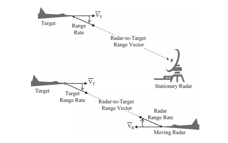
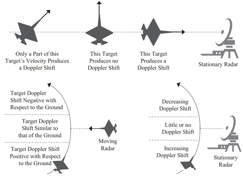
As shown in the figure, when the radar system itself is also moving, the velocity on the distance vector between the target and the radar is actually the projection value of the target velocity vector and the radar velocity vector in the direction of this distance vector. This means that the final measured velocity comprehensively reflects the influence of the motion state of both the target and the radar, that is, the radial component of their relative motion.
1. Pulse Doppler frequency shift velocimetry method
Radar systems use various methods to measure the velocity of targets, among which pulse Doppler frequency shift velocimetry is a commonly used technique. This method calculates the velocity of the target relative to the radar by analyzing the pulse Doppler frequency shift in the received target reflection signal. Specifically, when the target moves towards or away from the radar, the frequency of the electromagnetic waves reflected back to the radar will change, and this change is proportional to the speed of the target. By accurately measuring this frequency shift, the radar system can determine the velocity of the target and evaluate the relative motion relationship between the target and the electromagnetic waves emitted by the radar.
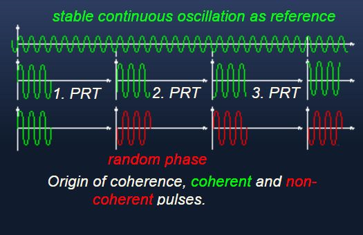
In order to accurately measure Doppler frequency shift, the radar system uses coherent pulse train signals. This method requires precise carrier and modulation processing of the received waveform during signal generation, transmission, and reception to ensure phase consistency and accuracy. In this way, radar can effectively detect small frequency changes caused by target motion, thereby achieving accurate measurement of target velocity. The key to this method is to maintain the coherence of the signal, that is, to maintain the continuity and stability of the signal phase throughout the entire processing process.
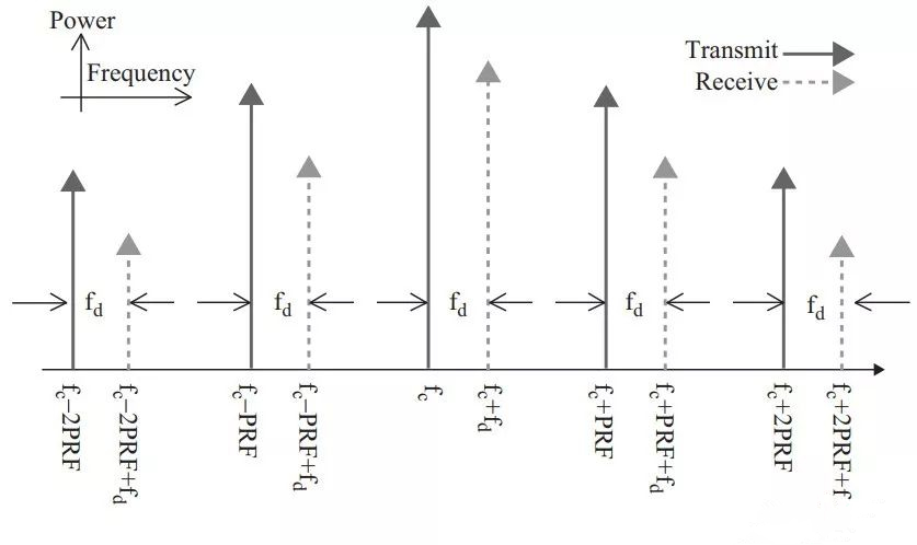
As shown in the above figure, when the target is in motion, the frequency spectrum of its echo signal will undergo Doppler shift. By measuring this frequency shift, the velocity of the target relative to the radar can be calculated. According to the principle of Doppler effect, when the target approaches the radar, the radar wave is compressed, resulting in an increase in the frequency of the echo; On the contrary, when the target moves away from the radar, the radar wave is stretched, causing the frequency of the echo to decrease. Therefore, in the symbol representation of Doppler shift, negative velocity (i.e. moving the target towards the radar) will result in positive Doppler shift, while positive velocity (i.e. moving the target away from the radar) will result in negative Doppler shift.
For example, if the target’s speed is 150 meters per second and the radar wavelength is 0.03 meters, the resulting Doppler frequency shift is 10 kilohertz. The negative value of the speed here is because the target is moving towards the radar, causing the distance between the two to shorten. The following figure shows the Doppler frequency shift of the radar carrier frequency at unit velocity.
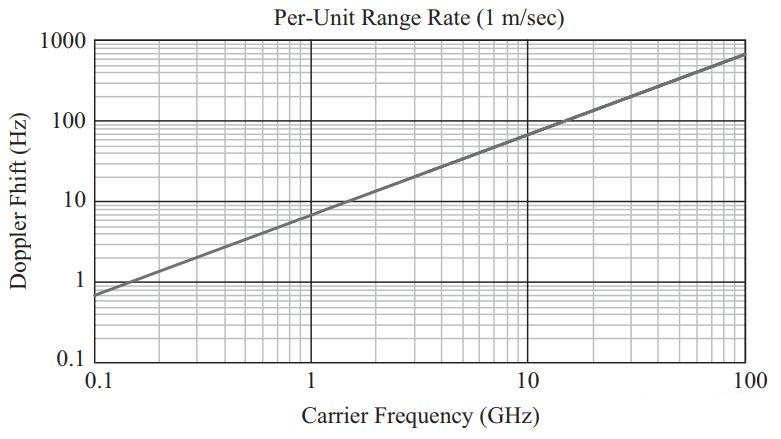
From the graph, it can be seen that the higher the frequency of the radar wave, the greater the Doppler shift value generated. Although radar designers cannot control the speed of targets, they can increase frequency shift and improve measurement accuracy by selecting higher radar frequencies. This is also one of the reasons why most Doppler radars use high frequencies. In addition, the relative geometric position and motion direction between the target and the radar also significantly affect the magnitude of the Doppler shift, as shown in the figure.
2. Doppler filter group
The calculation of Doppler shift can be achieved through a series of connected narrowband matched filters. Among these filters, only the one that contains the target Doppler frequency shift will have a higher signal-to-noise ratio in the output signal, while the other filters mainly contain receiver noise. In the threshold detection stage, the system will check the output of each Doppler filter one by one to determine the velocity of the target.
Usually, the design of Doppler filters involves overlapping the bandwidth of adjacent filters by approximately half of the power bandwidth, so that a continuous set of Doppler filters constitutes a Doppler filter group that can comprehensively cover all possible Doppler frequency shift ranges that the target may produce. For target surveillance radar that needs to monitor large-scale velocity changes, the required number of Doppler filters may be very large.
3. Speed resolution
Narrowband filters select specific Doppler frequency shifts by integrating the signal over a certain period of time. The longer the integration time, the narrower the bandwidth of the filter and the higher the velocity resolution. This integration time is called the pulse train period or coherent processing interval (CPI).
The speed resolution is related to the bandwidth of the Doppler filter. For example, if the bandwidth of the Doppler filter is 200Hz and the wavelength of the radar transmission signal is 0.03 meters, then the velocity resolution of the radar is 3 meters per second. This means that the radar can distinguish a minimum speed difference of 3 meters per second.
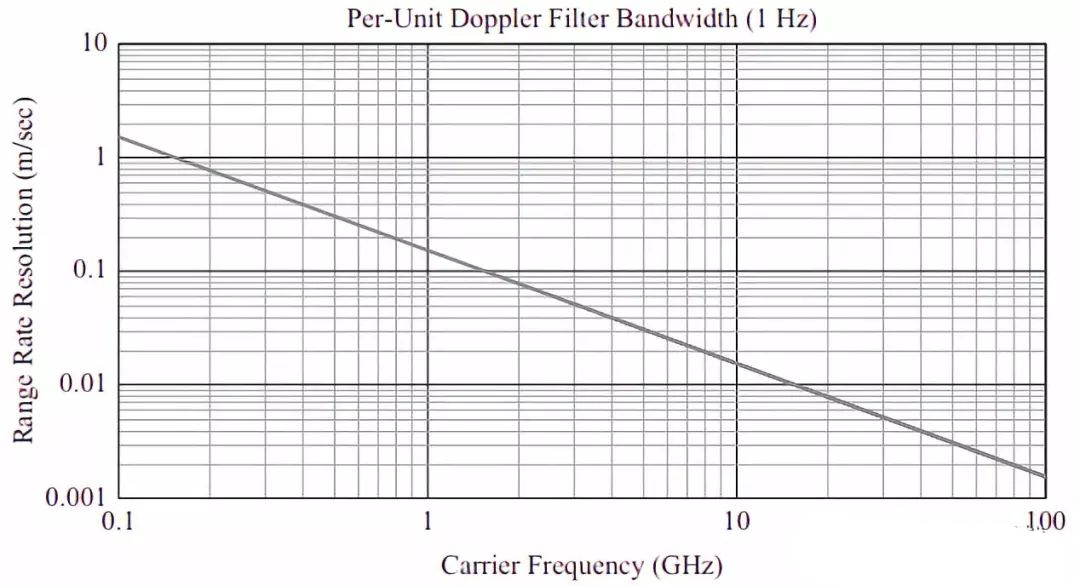
As shown in the figure, the velocity resolution per unit Doppler filter bandwidth is related to the radar carrier frequency. The higher the radar carrier frequency, the better the velocity resolution for the same Doppler filter bandwidth. This is precisely why most Doppler radars use high frequencies. The pulse train waveform can support excellent Doppler resolution, and its period can be adjusted according to specific needs. Therefore, radar design is a complex system engineering problem that requires comprehensive consideration of multiple factors.
4. Speed blur
The pulse train waveform may exhibit ambiguity in the frequency domain, where it is difficult to directly and accurately measure the true velocity of the target when the Doppler frequency shift exceeds a certain range. Radar systems measure Doppler frequency shift by using Doppler filter banks, whose frequency range typically matches the pulse repetition frequency (PRF). Therefore, when the Doppler frequency shift is within the range of ± PRF/2, there will be no velocity blur.
However, when the Doppler frequency shift exceeds the range of ± PRF/2, velocity ambiguity can be eliminated by subtracting an integer multiple of PRF from the measured frequency shift and remapping it back to the range of – PRF/2 to+PRF/2. This process of converting from the frequency domain to the velocity domain ensures accurate velocity measurements even when there is a large Doppler shift.
To further address the ambiguity of distance or velocity, radar systems can adopt various strategies. A common method is to use multi PRF technology, which means alternately using different pulse repetition frequencies in the same system. This can introduce ambiguity within one measurement interval and avoid ambiguity in another interval. Another method is the continuous PRF technique, which first uses one PRF for distance measurement, followed by another PRF for speed measurement, or vice versa, to overcome the ambiguity of distance or speed.
5. Speed tracking
Speed tracking, as a function of time, represents following the speed of the target, that is, measuring the continuous change in speed. The ‘tracking gate’ can track targets with specified speeds around it. Radar systems can automatically track targets through closed-loop control systems, or manually track them through operators, or a combination of both. In addition, the output of the Doppler filter group of the radar system can be selectively monitored and viewed.
Velocity measurement tracking is achieved by following the Doppler movement of the target in the time domain. When a single target is tracked, this commonly used speed tracking technique is called “speed gate”. This technology can distinguish the receiving target between two narrowband Doppler filters.
